Technical: Wire and Cable Routing
Jim Garrett, Stan Diener, Kurt Melancon, Dave Hennessey
1952-1956 K & KH
1957-1958 Sportster XL & XLH
|
1954-1955 Colorized Diagram 
|
The wiring for these models changed very slightly during these years. Download and print the correct diagram for your year/model. These diagrams are reprinted from the Rider's Handbooks of 1952, 1954, and 1957.
1952-1953 Wiring Diagram and Key
1954-1955 Wiring Diagram and Key
1956-1958 Wiring Diagram and Key
The 1957 Wiring Diagram and Key are the cleanest copy we have, so we'll use them throughout this article, and note the changes for other years. We'll use Harley's Descriptions of [Cable] A - H (slightly modified for clarity) for consistency.
|
1957 Wiring Diagram Key (for looms) 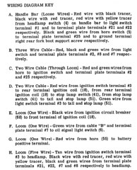 |
1957 Wiring Diagram  |
Here are the set of wires needed for these models...
|
Headlight switch - Cable A - Horn switch  |
Cable A A. Handle Bar (Loose Wires) - Red wire with black tracer, black wire with red tracer, red wire with yellow tracer from headlamp switch (4) on handle bar to light switch terminal #1 and to terminal plate terminals #21 and #22 respectively. Black and green wire from horn switch (5) to terminal plate terminal #25 and to ground terminal right rear fork boot support screw respectively.
Headlight toggle switch wire: 70100-51
|
|
Cable A notes:
* The Horn switch wire used 1952-1953, was a single “black” wire. When pressed, the horn switch grounded the horn to the handlebars. Apparently, there was a problem with the ground going through the rubber bushing handlebar mounts. In 1954, a green ground wire was added. This ground wire attached to the base of the switch, and was fastened to the right rear fork boot support screw. * The horn switch “black” wire was black with white tracer in 1952-1953. In 1954 it switched to black. Later, it may have switched back. The 1957 Riders Handbook is inconsistent - the Wiring Diagram shows black with white tracer, but the Wiring Diagram Key says black. |
|
|
Cable B  |
Cable B B. Three Wire Cable - Red, black and green wire from light switch and terminal plate terminals #2, #8 and #7 respectively.
Regulator to fork cable
|
|
Cable B notes:
* The differences beween the three versions of this cable are not known at this time. |
|
|
Cable C  |
Cable C C. Two Wire Cable (Through Loom) - Red and green wires from horn to ignition switch and terminal plate terminals #2 and #25 respectively.
Horn to fork terminal cable
|
|
Cable C notes:
* The differences beween the two versions of this cable are not known at this time. |
|
|
Cable D - 1952-1955  |
Cable D - 1952-1955 D. Two Wire Cable - Red wire from Ignition switch terminal #3 to rear terminal ignition coil (18), from rear terminal ignition coll (18) to stop lamp switch (41), from stop lamp switch (41) to tail and stop lamp (51). Green wire from light switch terminal #3 to tail and stop lamp (51).
Ignition and tail lamp cable - 1952 - 1955
|
|
Cable D notes:
* The differences between the -52 and -52A are not known at this time. |
|
|
Cable D - 1956-1958  |
Cable D - 1956-1958 Cable D is now four separate cables
|
|
Cable D notes:
* The 1956-later taillight socket came with a length of wiring. These wires were joined to the two new tail light wires. |
|
|
Cable E  |
Cable E E. Loom (One Wire) - Black wire from Ignition circuit breaker (68) to front terminal of Ignition coll (18).
Timer to spark coil cable assembly
|
|
Cable E notes:
* Shown in the Circuit Breaker section of the Spare Parts Catalogs |
|
|
Cable F  |
Cable F
F. Loom (One Wire) - Green wire from cable "B" and terminal plate terminal #7 to oil signal light switch (6).
|
|
Cable F notes:
* Some oil signal light switches used a clip-on connector, some used an eyelet connector with a screw. Specify which one when you order your wiring harness set. |
|
|
Cable G  |
Cable G G. Loom (One Wire) - Red wire from horn (55) to battery positive terminal.
Horn to battery cable
|
|
Cable G notes:
* |
|
|
Cable H  |
Cable H H. Loom (Five Wire) - Tan wire from Ignition switch terminal #3 to headlamp. Black wire with red tracer, red wire with yellow tracer, black and green wires from terminal plate terminals #21, #22, #7 and #8 respectively to headlamp.
Headlamp wiring complete
|
|
Cable H notes:
* Shown in the Headlamp section of the Spare Parts Catalogs |
|
|
Cable W 
|
Cable W W. One wire - Red wire from Light Switch (16) terminal #2 to Ignition switch (15) terminal #2.
Switch connecting cable
|
|
Cable W notes:
* Single wire, not a loom. |
|
|
Cable X  |
Cable X X. One wire - Black wire from battery negative terminal to ground terminal on frame.
Battery ground cable
|
|
Cable X notes:
* Single wire, not a loom |
|
|
Cable Y  |
Cable Y Y. One wire - Black wire from Voltage Regulat “F” terminal to Generator “F” terminal.
Generator Field Wire
|
|
Cable Y notes:
* Single wire, not a loom |
|
|
Cable Z  |
Cable Z Z. One wire - Red wire from Voltage Regulator “Gen” terminal to Generator “Reg”
Generator Output Wire
|
|
Cable X notes:
* Single wire, not a loom |
|
Continue to Wiring and Routing